
产品详情


M100

M100 Series
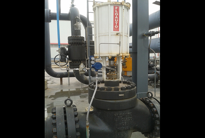
Pneumatic High-Pressure Labyrinth Control Valve
Main Technical Parameters
Design Features of MAZE100 Control Valve
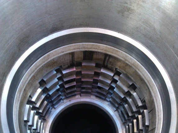
- Each cage is fabricated by bonding multiple layers of labyrinth discs using a special process. Every labyrinth disc is machined with a number of labyrinth-like flow channels via a special forming process. Based on various service conditions, each flow channel is precisely calculated with CFD flow field analysis and designed with a specific number of right-angle bends. These bends generate fluid resistance for gradual pressure reduction, limiting the medium velocity below 30 m/s. This keeps the medium pressure consistently above the saturated vapor pressure, eliminating cavitation, flashing erosion, vibration, noise and other related issues.
- The design of each labyrinth disc is customized according to process conditions including differential pressure, flow rate and control characteristics of the user’s system. Labyrinth discs with different pressure reduction stages (up to 60 stages), different numbers of flow channels, different inlet areas and different layer counts are assembled to form a custom cage. This not only maintains controlled fluid velocity, but also enables precise flow regulation to achieve optimal control performance.
- Numerous small inlets are distributed around the outer circumference of the labyrinth cage, acting like a filter screen to block welding slag and other contaminants from entering the plug and seat area, preventing plug jamming and sealing surface damage. Thanks to the small inlet openings and slightly enlarged outlets, fluid flows rapidly. Fine particles entering the inlets will be flushed out quickly, while large particles are unlikely to clog the inlets. Even if temporary clogging occurs, the labyrinth cage is designed with sufficient margin so flow shortage will not happen.
- A weir structure is adopted at the outlets of labyrinth disc flow channels. It equalizes local pressure around the plug and eliminates radial forces on the plug that may cause sticking, binding, radial vibration or flutter. This keeps the plug well centered. Fluids discharged from upper and lower flow outlets interact with each other to avoid direct medium impingement onto the sealing surface.
- A uniquely designed seat is used. The contact surfaces between plug and seat have different angles to form line-contact sealing. Combined with the high driving force of the actuator, circumferential indentations are formed on the seat ring. Such indentations remove tiny scratches caused by fine particles carried in the fluid, enabling reliable, repeatable long-term shutoff of the valve under high differential pressure.
- In principle, balanced plugs may be used for large-size valves with high differential pressure to reduce opening thrust. Unbalanced plugs can be adopted for high-temperature and small-size valves to minimize internal leakage.
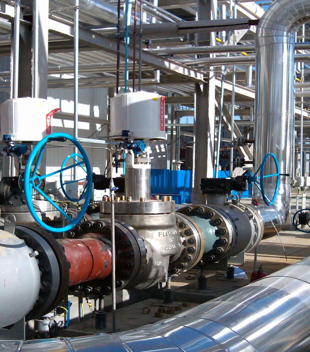
Application of MAZE100 Control Valve in Natural Gas Processing Units
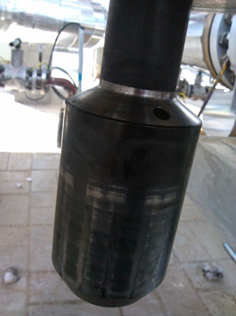
After five years of service, the valve trim components of the MAZE100 control valve, such as the valve cage and valve plug, remain in excellent working condition as-delivered from the factory.